Contact
Write to Us And We Would Be Happy to Advise You.
Do you have any questions, or would you like to speak directly with a representative?
By hqt
Let’s say we need to give commands to our device. The easiest way to do this is through ordinary buttons hung on the port. But it’s one thing when there are two or three buttons, and another when there are twenty of them. Do not kill for the sake of these twenty controller outputs. There is a solution to the problem membrane 3×4 matrix keypad.

That is, the buttons are grouped into rows and columns, and the resulting matrix sequentially interrogate by the microcontroller, which makes it possible to drastically reduce the number of required outputs at the cost of complicating the polling algorithm.
I drew it for you in the first picture. As you can see, there are rows and columns. Buttons circle. They included so that when pressed, the button closes the row with a column.
The read port enables in Pull-up input mode, that is, an input with pull-up resistors. If the controller does not support this, then these resistors must be hung outside.
The columns of membrane 3×4 matrix keypad must pull up by resistors to the power supply. However, if a full-fledged Push-Pull is common, then a lift does not need – the exit itself will raise the leg to the desired level.
Works as follows.
A value consisting of one zero and one on all other pins is output to the scanning port. Let, for example, zero be at output A. The presence of zero immediately presses down the pull-up and the entire column falls to the ground.
If no button presses on column A, then all ones will be in the port. But it is worth pressing any button from column A, so it will immediately close line A to this port pin. In line A, we currently have 0, this provides a zero on the scan output of the controller. Therefore, the corresponding port pin will also be 0.
So, if a button is pressed, for example, 6, then the P1 line will be 0.
Then the number in the membrane 3×4 matrix keypad shift one bit to the left (or right) and the second column scan, and so on in a circle. As a result, knowing which column we are scanning, having received zero on the reading port, we, as by coordinates, will understand which button from the matrix press.
You can determine the simultaneous pressing of many buttons – you just need to check not by byte, but by a specific bit.
But what if we have not just a lot of buttons, but a lot. That even matrixing does not save from the huge consumption of port lines. Here you have to either sacrifice several ports, or introduce additional logic. For example, a decoder with an inverse output.
Decoder, this is such a microcircuit that takes a binary code as input, and outputs a unit to the selected bit at the output. Those filed the number “101” – received “1” at output number 5. Well, the inverse decoder will have 0.
You can go even further and put a microcircuit counter, which pull by a pulse from the port, the value from the counter is run through the membrane 3×4 matrix keypad. Thus, you can stick as many conclusions as you like, the bit depth of the decoder would be enough. The main thing to consider is on what cycle of the counter we will have which column.
If a regular keypad scan, pressed by a person, then you cannot bother with the polling speed and make it as a by-product, hanging it on some left interrupt. It is enough that the keypad poll at least 10-20 times per second. This is already enough for comfortable work.
When working with membrane 3×4 matrix keypad, one problem arises – contact bounce. Its essence is that when closing, the contact trigger more than once, but at the moment of closing and opening, several operations occur.
This comes from the fact that ideal contact does not occur immediately, but after some time, sparks and gnashes. Although this is not visible. So, it turns out that instead of one drop, we first get a series of bursts and only then does a stable state arise.

What is membrane 3×4 matrix keypad?
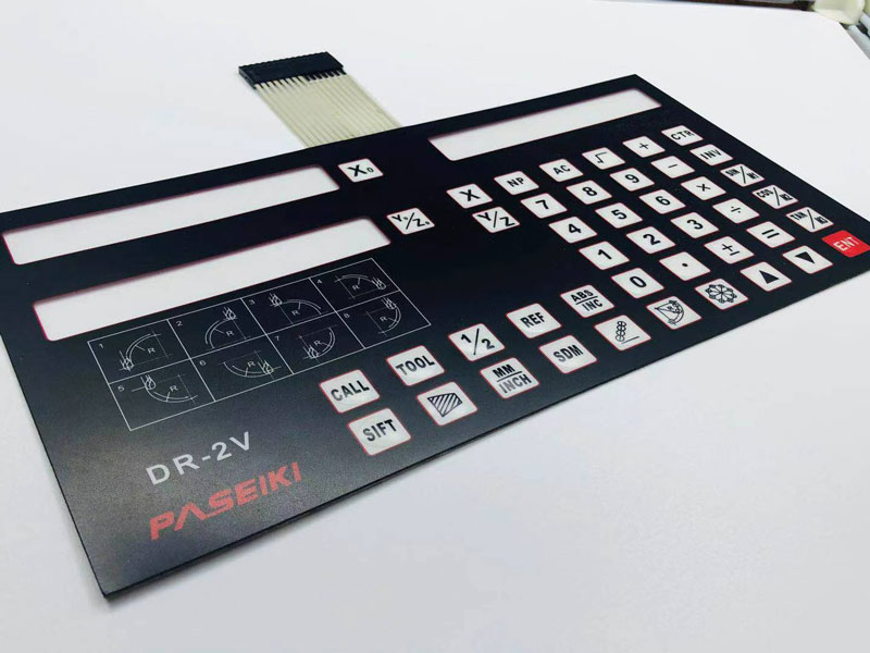
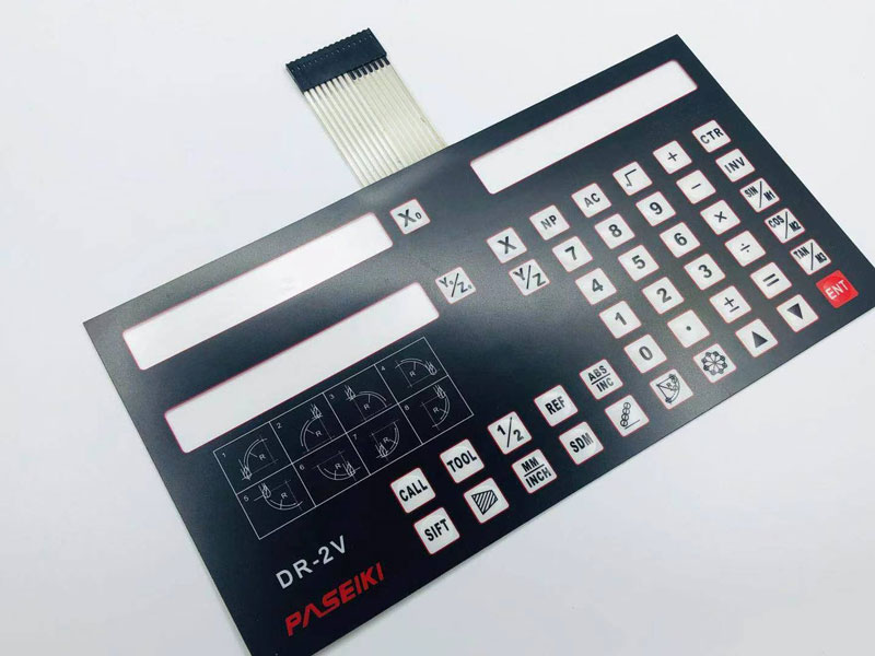
This membrane keypad has 20 buttons, ten of which are numbers, and the rest are special characters: “Enter”, “Exit”, “*”, “#” and four multidirectional arrows.
This keypad attaches to any surface using an adhesive layer applied to the back of the module. A convenient 9-pin connector allows you to securely connect the keypad to the desired device, ensuring stable operation.
The voltage limit is 250 V, which the keypad can withstand for a minute without damage. The current consumption in the operating mode is 100 mA.
But the microcontroller works at such a speed that it manages to count these bursts as steady states. This problem can solve by hardware, using the RS trigger, or by software – by introducing a small delay before the next poll of the button. The delay select so that the bounce has time to stop by the end of it.
The mechanism of the membrane 3×4 matrix keypad determines the depth of depression, smoothness, sound, feel when used. It selects depending on the purpose of the keypad and personal preferences. There are two types currently on the market:
Membrane keypads, they are also called laptop keypads – quiet, soft with a small key travel. Such keys design for typing, and are also often found on multimedia keypads. The main drawback is a small resource for the number of clicks in budget models.
Do you have any questions, or would you like to speak directly with a representative?